Dive lights and Battery Life March 29, 2009
Posted by Chris Sullivan in Equipment.Tags: Battery Life, CR123, Dive Light, Dive Torch, Diving, LED, LED Flashlight, Lithium Battery, SCUBA, Scuba Diving, Scuba Equipment, Scuba Light, Underwater Light
trackback
Continuing on from my description of my new (to me) OMS Vega V191 dive light, I would be interested in figuring out when to replace the batteries. With new batteries, this light runs for 3 hours. So the first challenge is to determine how much life is left in a used set of batteries. I don’t know if this can be done reliably, but I am going to set out to find out.
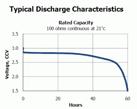
Energizer provides a data sheet for their CR123 Lithium battery, which shows the change in voltage over time as the battery drains. I should point out that the term Lithium battery is somewhat colloquial in this respect because there are many types of Lithium battery, and this particular one (like all the other brands) is a Lithium Manganese Dioxide cell. This curve uses a load of 100Ω on the battery, a standard used for the purpose of testing batteries. Using the relationship between power (P), voltage (E) and resistance (R) of P=E²/R the power output of the battery starts at .09 watts, dropping to about .08 watts when the battery quickly declines to around 2.85V. I used this simple calculator to apply the formula to these examples.

Energizer 123
In the last 20 hours of the battery’s life, the voltage declines further reaching 2.5 volts after about 53 hours of continuous operation. At this point we’re seeing just over .06 watts output, down a third from the 3 volt level.
The voltage then drops precipitously in the final hours.
My dive light uses two batteries in series for an output of 3 watts, which is much greater than this test. The resistive load of the LED would be a mere 12Ω at this output with the full 6 volts. OMS documentation says that
A few questions come to mind…
- What is the minimum voltage that the light needs to operate? I’ll be able to answer this once I flatten a set of batteries to the point where the light stops operating. To do this, I’ll have to use the light as a primary light with a separate set of batteries for dives where I don’t need it as a standby. I measured the used ones that the light came with at 2.855 and 2.845 volts (under zero load), so I will use these. I have another set lying around that are at 3V, which I’ll use when I really need the light for a standby. According to Wikipedia, white LEDs start to emit light at 3.5 volts and above. The Marl LED Technical Library shows illumination starting at 5.5 volts, so it will be interesting to discover what the truth is.
- Is the discharge curve the same shape under the heavier load of the light. Instead of .06 to .09 watts, for 1.5 watts the resistance for a single battery is a mere 6Ω. At this level of output the voltage at the flat part of the curve (in the 100Ω example this is the first 30 hours) might be less than 2.85. That’s hard to tell without testing, and I don’t really want to burn up batteries just to do that.
- What is the relationship between light output and voltage? LEDs have a pretty linear relationship between voltage and output, although high power LED applications use voltage regulators to keep the voltage constant so that the LED does not draw to much current and overheat. I noticed on a UK lights LED underwater light that there was a fair bit of circuitry built into the head.
- Can the no-load voltage of the batteries be used to track where the battery lies on the discharge curve? I imagine I could test a battery with zero load, 6Ω and 100Ω separately and see how the readings vary (I own a very accurate & precise Fluke DMM).
Question #1 will be answered in time once my weaker set of batteries fails to produce light from the LED. I’ll simply have to measure the combined voltage of the two batteries to answer that question. With this information and measurements over time I can plot the decay of the voltage with time and use.
I might end up working on #2 after doing some of the other projects.
I’m thinking about checking #3 with using the lightmeter of my camera, an old Nikon FE. It would require that I construct a jig to ensure that I can reproduce the setup to test the light at different voltages.
The final test would be to see if the voltage of the battery is different under load. That would help calibrate the battery against the discharge curve. At 100Ω the power is low enough that a 1/2W or 1/4W resistor would be just fine for the test.
Should be interesting. I’ll keep you posted.
Comments»
No comments yet — be the first.